
TB 9-2320-280-35-9
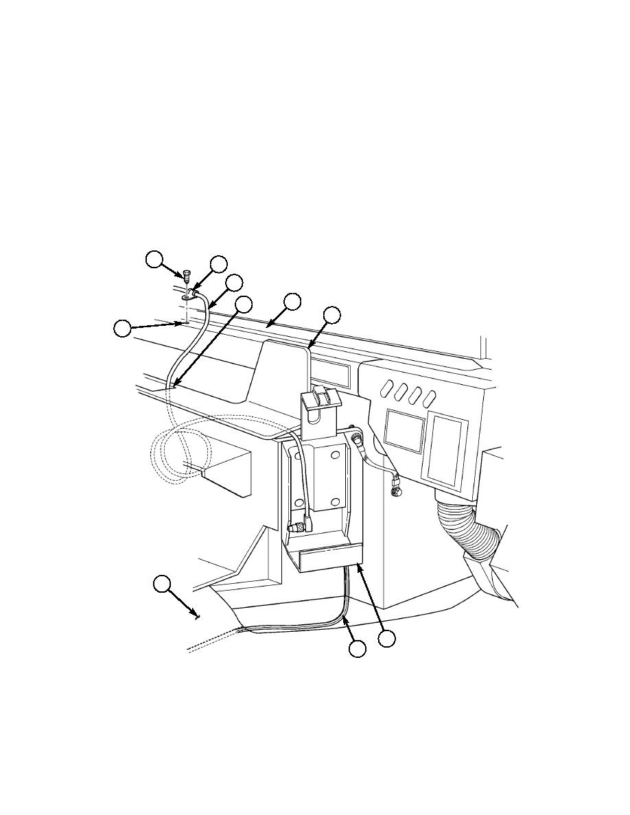
22-17. Locate, mark, and drill one 0.147-in. hole (34) in top of windshield frame (29).
22-18. Route PLGR antenna cable (7) on top of windshield frame (29) and secure with loop clamp (25) and
self-tapping screw (24).
22-19. Route PLGR antenna cable (7) down through center access hole (28) of integrated rack (30), and
coil excess antenna cable (7) under integrated rack (30).
22-20. Route PLGR power cable (32) from PLGR installation mount (31) to right-side tunnel
insulation (33).
NOTE
Loosen right-side tunnel insulation before performing step 22-21.
(Refer to TM 9-2320-280-20.)
22-21. Route PLGR power cable (32) under edge of right-side tunnel insulation (33) to 24V terminal bar at
cab enclosure panel.
24
25
7
29
28
30
~
34
33
31
32
24. SELF-TAPPING SCREW 9421073 QTY. 1
25. LOOP CLAMP MS21333-65 QTY. 1
32. PLGR POWER CABLE 9728558-10 QTY. 1
Figure 5-60.
5-51

