
TM 11-6130-392-34
3-5. Voltage, Resistance, and Waveform Measure-
3-4. Repainting and Refinishing
ments
Fault isolation procedures are specified in para-
Touchup of small damaged areas of the battery charger
graph 3-12. Procedures specify when voltage, resis-
case and equipment case is authorized at direct support
tance, or waveform measurements are to be made,
level. Refer to TM 11-6130-392-12, operator and
and which test points to be used. Illustrations are
organization; maintenance manual, for instructions.
provided for identity and test point locations.
Section II. TOOLS AND EQUIPMENT
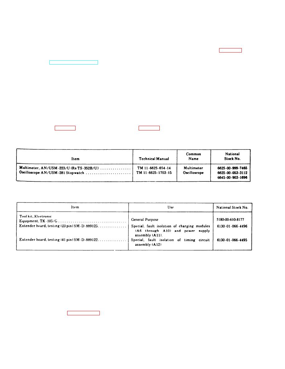
3-6. Test Equipment, Tools, and Materials
b. Tools and Materials. Tools and materials re-
a. Test equipment. Test equipment required for
q u i r e d for direct support maintenance, including
special tools required for fault isolation, are listed in
direct support maintenance of Battery Charger PP-
7286/U is listed in table 3-1.
Table 3-1. Test Equipment
Table 3-2. Tools and Materials
Section III. TROUBLESHOOTING
3-7.
Troubleshooting-General
3-8. Troubleshooting Test Sequence
This section contains instructions for troubleshooting
a. Visual inspection. Before performing tests,
Battery Charger PP-7286/U. Direct support personnel
visually inspect the battery charger to find faults.
will replace faulty components, which are limited to the
Prevent tests that are not necessary to locate an
specific list contained in paragraph 3-3. Replacement
easily-seen fault.
procedures are included in section IV. Test procedures
b. Test sequence. The test sequence for trouble-
for use after replacing a component are included in sec-
shooting the battery charger and isolating faulty
tion V.
components, is:
3-2 Change 1
