
TM 11-6130-392-34
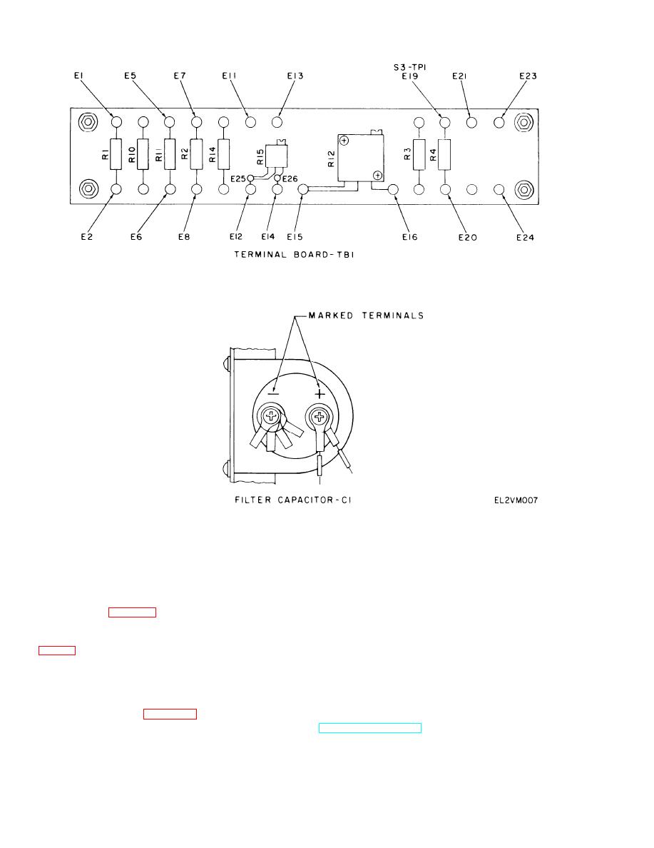
Figure 3-3. References and Locations, Battery Charger PP-7286/U
send battery charger to next higher maintenance
Test 4. Memory Battery (B1) Sensor Resistor Test.
level.
a. Set POWER switch to ON.
(2) Does not show current flow; set POWER to
OFF, return to table 3-3.
c. Connect negative () lead of multimeter to
negative () terminal on capacitor C1 (fig. 3-3).
j. Set POWER switch to OFF. Remove oscillo-
scope probe from A12-32 and connect to A12-TP2
d. Connect positive (+) lead of multimeter to
TB1-E7 (fig. 3-3) and observe multimeter.
k. Set POWER switch to ON. Measure DC volt-
( 1 ) If meter reading is 7.0 volts or more,
age.
d i s c o n t i n u e testing and send battery charger to
next higher maintenance level.
(1) If DC voltage is 7 VDC or more; set
POWER to OFF, replace A12 timing circuit
(2) If meter reading is less than 7.0 volts, set
assembly (Section IV, para 3-16), and go to section
POWER switch to OFF. Replace memory battery
V.
(TM 11-6130-392-12). Go to section V.
(2) If DC voltage is less than 7 VDC; discon-
Test 5. Display Circuit Assembly (A13) and
tinue testing, send battery charger to next higher
Display Modules (U1, U2, U3) Test.
maintenance level.
a. Check display reading.
3-8
