
TM 11-6130-392-34
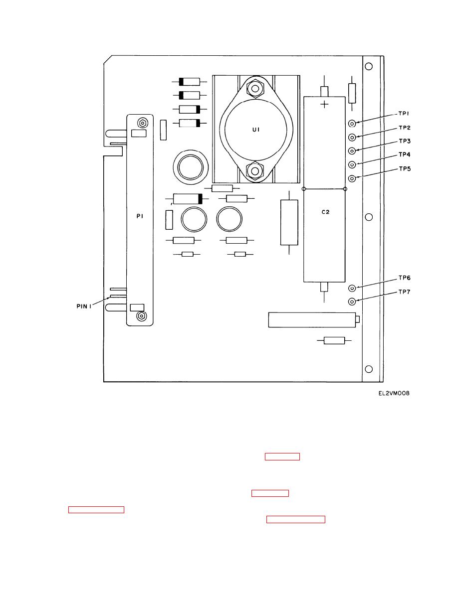
Figure 3-4. Power Supply Assembly (A11) Terminal and Test Point Locations
is still blank; set POWER to OFF, and replace this
(1) If any display modules are blank; go to step
b.
faulty display module and reassemble A13 (Section
IV, para 3-17). Go to section V.
(2) If at least one display module reads same as
t h u m b w h e e l switch setting, and no modules are
(2) If display module, that was blank in step a.,
blank; go to step d.
i s now reading correctly; set POWER to OFF,
(3) If all three display modules read wrong
replace timing circuit assembly A12 (Section IV,
digit; go to step l.
b. Set POWER switch to OFF. Refer to section
A13. Go to section V.
IV, paragraph 3-17; dissemble A13, and interchange
d. Set POWER switch to OFF. Refer to section
module showing blank with one that is not blank.
I V , paragraph 3-17 for maintenance instructions
c. Set POWER to ON. Press START TIME
and interchange the good display module with one
switch.
that reads wrong.
e. Set POWER switch to ON. Press START
(1) If display module that was blank in step a.,
3-9
