
TM 11-6130-381-14
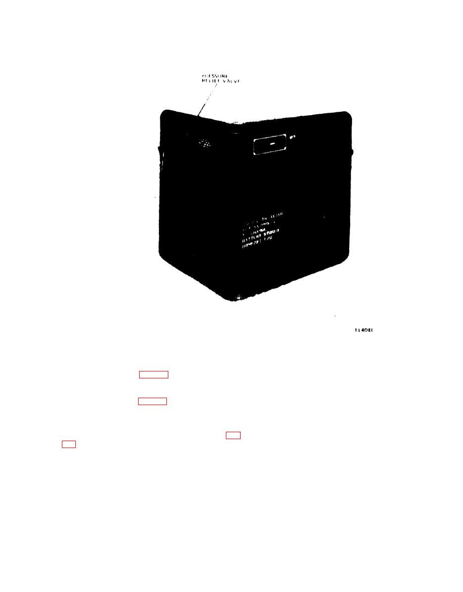
Figure 1-2. Charger, Battery PP-4127B/U, cover closed
wide. Operating
controls and
indicators for the
1-8. Description of
Equipment
battery charger are mounted on the front panel.
battery charger (fig. 1-1) is a self-contained,
No carrying handles are also located on the front
p o r t a b l e unit housed in a metal, waterproofed,
panel. The hinged cover of the transit case stores
hermetically sealed transit case. A two way
the 8-foot long input power cable as well as the 230
pressure relief valve (fig. 1-2) at the center of the
vac conversion assembly for the battery charger.
t i n t of the transit case prevents any excessive
T h e power cable is terminated in a heavy-duty,
pressure buildup inside or outside the transit case.
three-wire, connector plug. All the spare parts for
A gasket and wire mesh provide a water seal
t h e battery charger are included in the field
between the front panel and the transit case (fig.
maintenance kit for Radar Set AN/PPS-5.
inches long, 12 3/4 inches high, and 10 1/4 inches
1-9. Technical Data
Input power:
115 or 230 volts 10 percent; 60 or UMl Hz
voltage
5 percent.
Single.
Phase
2.5 amperes (full load 115 volts ac), or 1.3
Currant (maximum)
amperes (fuIl load, 230 volts ac).
Full load, two batteries being charged: ap-
Power consumption
proximately 220 watts maximum.
1-3
