TM 11-6130-381-14
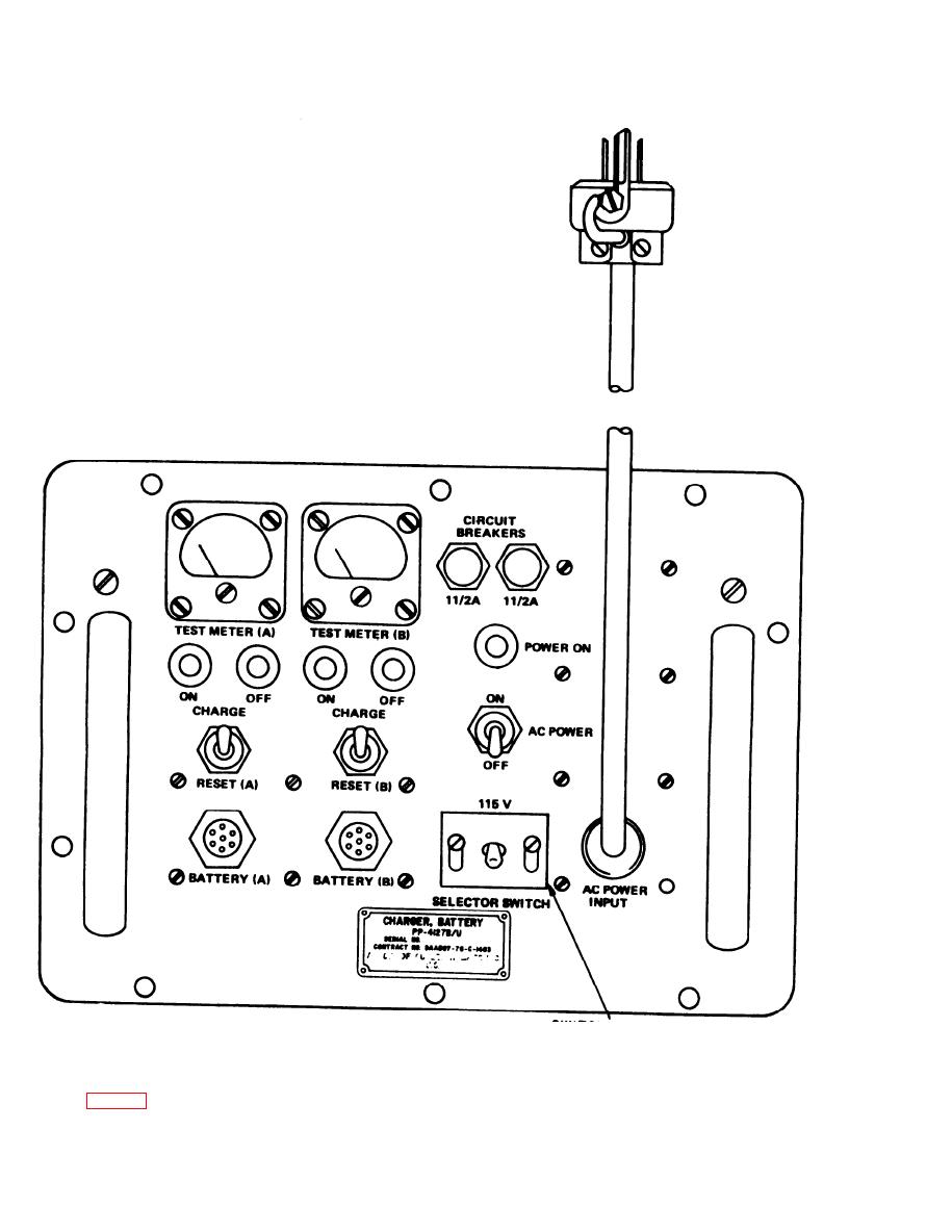
Figure 2-2. Battery charger, controls and indicators.
2-4. Preliminary settings
two screws to set the SELECTOR SWITCH in the
up position for 230-volt operation or in the down
Two screws lock the SELECTOR SWITCH in
position for 115-volt operatipn. Tighten the screws
either the 115 V or the 230 V position. Loosen the
to lock the switch in position. In the up position,
2-4


